| Home | Energy | Nuclear | Electricity | Climate Change | Lighting Control | Contacts | Links |
|---|
INTRODUCTION:
This web page is concerned with choice of a fuel tube alloy that gives a long fuel tube working life in a fast neutron flux while also meeting other required performance constraints.
Reference:
A Review of Failure Modes of Nuclear Fuel Cladding
AVOIDING FUEL TUBE INTERNAL CHEMICAL CORROSION:
In practical FNR designs the fissile fuel is localized tto the center of the reactor to avoid exposing the pool enclosure walls and intermediate heat exchangers to a neutron flux.
In a CANDU reactor, which fissions about 1% of its core fuel weight per fuel cycle, the fuel is changed every 18 to 24 months due to accumulation of of slow neutron absorbing fission products. However, a FNR is much less sensitive to fission product accumulation and fissions about 15% of its core fuel weight per fuel cycle. In order to achieve this increase in fuel burnup, the FNR fuel cycle is typically 25 to 30 years long. Over this long fuel cycle it is essential to avoid chemical corrosion of the fuel tubes.
One of the challenges is that all FNRs use either pure uranium or a uranium alloy as core fuel. Uranium has two chemical valence states, +4 amd + 6. Hence uranium in combination with oxygen forms either UO2 or UO3. Similarly, uranium in combination with chlorine forms either UCl4 or UCl6. If the fuel rods contain any UO3 or UCl6 over time those compounds can change into UO2 or UCl4 releasing an active oxygen or chlorine atims that can potentially corrode the fuel tubes from the inside. The simple solution to this problem is to use metallic fuel rods.
SUMMARY:
Internal chemical corrosion of fuel tubes by fuel is avoided by use of metallic fuel rods. Similarly, internal chemical corrosion of fuel tubes by fission products is avoided by adding a surplus of metallic sodium to the contents of each fuel tube. That metallic sodium will preferentially absorb corrosive fission products. This metallic sodium also improves heat transfer from the fuel rods to the inner wall of the fuel tubes.
In a sodium cooled FNR there is metallic sodium on the outside of the fuel tubes which prevents corrosion of the fuel tube outside surface.
In a molten salt cooled FNR the metallic components of the molten salt must be chosen to prevent corrosion of the fuel tube outside surface. There may need to be some metallic Na mixed in with the blanket salt coolant as a corrosion inhibitor.
EFFECTS OF FAST NEUTRON IMPACTS ON FUEL TUBE ATOMS:
The effects of fast neutron impacts on fuel tube atoms are:
1) Addition of energy to the fuel tube material lattice which reduces the depth of its crystal lattice binding energy wells and hence reduces the material strength. This material strength reduction relates to the material's yield stress Sy;
2)The effect of the fast neutron impacts is to reduce the fuel tube atom binding energy implying that the lattice becomes less dense. If the lattice is initially fcc it will tend to rapidly change to bcc which causes rapid volumetric swelling. If the lattice is initially bcc the fast neutron exposure required to cause an equal amount of material volumetric swelling is much larger. Hence FNR fuel tubes should be made of metals have a bcc crystal lattice over the entire material operating temperature range.
3) Rapid and severe fuel tube alloy swelling occurs if there is a FCC to BCC phase transition;
4) Unacceptable fuel tube swelling also occurs on a BCC alpha to BCC (alpha + alpha prime) phase transition. This issue restricts the Cr fraction in the fuel tube alloy.
5) The fuel tube material becomes brittle if the fuel tube alloy contains any nickel. The relevant nuclear reaction sequences are believed to be:
Ni-58 + n = Ni-59
However, Ni-59 has a very large neutron absorption cross section which in a continuing neutron flux will rapidly cause:
Ni-59 + n = Ni-60 excited > Fe-56 + He-4
(alpha particle decay, Ref. Kirk Sorensen 2020 video)
The He-4 accumulates in metal grain boundaries and causes metal embrittlement. Hence Ni must be eliminated from the fuel tube alloy and any other alloy exposed to the neutron flux. For the FNR discussed herein the fuel bundle must be made of Fe-Cr.
Since Fe-Cr loses strength at high temperatures the maximum working temperature is limited.
A potential source of Ni is repeated neutron absorpion by Fe-56.
6) Above 700 degrees C the Cr becomes mobile in Fe. If there is any oxidizing element such as F or Cl in the fuel at high temperatures the uranium fuel component can change oxidation state from (IV) to (III) allowing formation of CrF2 or CrCl2 which together with Cr mobility will lead to a fuel tube failure. eg.Reference: A REVIEW OF FAILURE MODES OF NUCLEAR FUEL CLADDING
A secondary limit on the liquid sodium maximum temperature is the vapor pressure of sodium. The sodium vapor pressure adds to the partial presssure of argon, which increases the required argon bladder volume.
FUEL TUBE WEAR MITIGATION:
A key issue in prolonging fuel tube life is periodic fuel tube annealing. Fuel tube annealing is accomplished simply by removing the thermal load from the reactor so that the primary liquid sodium temperature and hence the fuel tube temperature gradually rises to about 550 degrees C. After a suitable annealing period the thermal load is restored.
CRYSTAL LATTICE ACRONYMS:
Common crystal lattice configurations are:
HCP = hexagonal close packed
FCC = face centered cubic
BCC = body centered cubic
FUEL TUBE SWELLING:
A key issue in making a Fast Neutron Reactor (FNR) economic is to minimize fuel tube swelling. An increase in fuel tube outside diameter (OD) due to fuel tube material swelling reduces the fuel bundle cross sectional area available for liquid sodium coolant flow, which reduces reactor power output and hence limits the practical fuel tube working life. The fuel tube mounting arrangements should accommodate substantial fuel tube swelling late in the working life of a fuel bundle. The fuel tube swelling mitigation methodology contemplated herein is to use a swelling resistant fuel tube alloy and to use a fuel bundle square tube lattice. Fuel tube swelling in a FNR is challenging because one of the FNR design objectives is to fission the fuel as long as possible to minimize the frequency of fuel reprocessing.
Experimentally, with the fuel tube material HT-9, the fuel tube volume increase at 15% fuel burnup is acceptable. However, HT-9 has issues related to temperature and neutron irradiation embrittlement. Relieving the embrittlement requires periodic fuel tube annealing.
A theoretical solution to the fuel tube problem is to use molybdenum fuel tubes which have a BCC crystal lattice and can be operated at a much higher temperature. However, molybedenum is difficult to form into fuel tubes and some molybdenum isotopes have high neutron absorbtion cross sections. Heence, molybdenum needs to first be isotopically separated,
It is helpful to understand the fuel tube swelling problem both in terms of fuel tube centre-to-centre geometry and in terms of the underlying causes of fuel tube swelling.
The increase in fuel tube diameter is caused by a combination of phenomena including:
a) Swelling of the fuel tube material caused by lattice dislocation formation within the fuel tube material;
b) Swelling of the fuel tube material due to the high thermal flux and high temperature causing material creep;
c) Swelling of the fuel rod inside the fuel tube due to formation of fission product gas bubbles within the fuel rod material;
d) Swelling of the fuel rod inside the fuel tube due to formation of two atoms in place of one during the fission process;
e) An increase in fuel tube internal pressure due to formation and trapping of inert gas fission products;
f) A change in fuel tube material phase from FCC to BCC if the initial alloy is not BCC, which is the lowest density crystal lattice.
These problems are aggravated by a decrease in fuel tube wall yield stress due to low nickel content, high operating temperature, fast neutron flux disruption of the fuel tube atomic constituants and spontaneous changes in the fuel tube crystal lattice.
The solutions to this fuel tube swelling problem include:
1) Use a fuel tube composed of metal isotopes with low neutron scattering cross sections;
2) Use a square fuel tube lattice instead of a staggered fuel tube lattice so that the impact of fuel tube swelling on the external primary liquid sodium coolant flow is low;
3) Use a fuel tube metal that has a low density BCC crystal lattice and no phase transitions in its operating temperature range.
4) Use of a fuel tube material with a high melting point that maintains a sufficient yield stress at the peak fuel tube operating temperature under fast neutron irradiation that it resists diameter expansion due to thermal and internal gas pressure stress;
5) Use of a fuel tube material with a relatively small Youngs modulus (modulus of elasticity) to minimize thermal stress in the tube material;
6) Use of a fuel tube material with a relatively high thermal conductivity to minimize thermal stress in the fuel tube material due to the radial thermal flux;
7) Use of core fuel rod and blanket fuel rod ODs that are sufficiently small with respect to the fuel tube ID that mechanisms (c) and (d) above have no effect on fuel tube hoop stress;
8) Use of a fuel tube metal wall that is sufficiently thick with respect to its ID that below the melting point of sodium the fuel tube can withstand the larger thermal expansion of sodium as compared to the fuel tube material;
9) Use of a large gas plenum at the top of the fuel tube to limit the inert gas pressure inside the fuel tube;
10) Provide sufficient additional plenum volume to allow for differential thermal expansion of liquid sodium;
11) Provide sufficient additonal plenum volume to allow for the extra sodium that is required as the fuel tube material swells in diameter;
12) Provide sufficient additonal plenum volume to allow for extra sodium that is required as the core fuel rod material swells in length;
13) Provide sufficient sodium to chemically absorb the fission products bromine and iodine as well as small amounts of other oxidizing elements such as chlorine, fluorine and oxygen.
The aforementioned fuel tube design keeps the maximum fuel tube material stress safely below the fuel tube material yield stress at all projected operating temperatures.
FUEL TUBE ALLOY CHOICE:
The fuel tube alloy optimization strategy is to prevent fuel tube swelling by choosing a fuel tube alloy crystal structure which remains in the same BCC (alpha plus alpha prime) phase at all times and to choose fuel tube constituant elements that have relatively low fast neutron scattering and absorption cross sections to minimize the fast neutron impact rate.
If the fuel tube crystal lattice is initially FCC a fast neutron impacts on the crystal atoms will cause a transition to a BCC like atomic density lower by as much as a factor of two and which causes a linear swelling dimension increase by as much as a factor of 1.26. With a staggered tube lattice this fuel tube material swelling can severely reduce the liquid sodium coolant circulation. The solution to this problem is to fabricate the fuel tubes from a 85% Fe-12% Cr alloy known as HT9 that under fast neutron irradiation remains BCC over a wide temperature range and hence has an insignificant atomic density change and to use a square fuel tube lattice.
DETAIL:
FNR fuel tubes are a key part of FNR design. The fuel tubes must be replaced every fuel cycle so the cost of fuel tube material, fuel tube fabrication, fuel tube material recycling and fuel tube irradiated material disposal are all significant issues. The fuel tube working life should be sufficiently long that it does not determine the frequency of FNR fuel reprocessing. One of the factors determining fuel tube working life is fuel tube alloy swelling.
Under sustained fast neutron bombardment FNR fuel tubes will eventually swell due to formation of metal crystal lattice dislocations.. However, tha amount and rate of swelling are dependent on the fuel tube element neutron scattering and absorption cross sections and on the fuel tube's initial crystal structure.
There are three common metal crystal structures: hexagonal close packed (HCP), face centered cubic (FCC) and body centered cubic (BCC). With HCP the number of atoms per unit volume is close to its theoretical maximum for a solid at atmospheric pressure. With FCC the number of atoms per unit volume is moderate. With BCC the number of atoms per unit volume is close to its theoretical minimum for a solid at atmospheric pressure.
The effect of fast neutron bombardment is to reduce the metal crystal structure atomic density. This reduction in atomic density increases the metal volume, causing swelling in three dimensions. Swelling due to fast neutron impacts can be minimized by choosing a fuel tube alloy that is initially BCC so that the primary mechanism for swelling is relatively ineffective. Hence the fuel tube alloy should be chosen so that it remains BCC throughout its working temperature range and working life.
CONSIDER THE NUMBER OF FISSION NEUTRONS EMITTED PER FUEL CYCLE:
From FNR Fuel Rods each core fuel rod has an initial mass of 0.362047 kg and is 0.45 m long. Hence in one fuel cycle the number of neutrons / m emitted by this fuel rod is:
0.362047 kg X 0.15 burnup X (6.023 X 10^23 atoms / 0.239 kg) X (3.1 neutrons / atom fission) / 0.45 m
= 9.4280 X 10^23 neutrons / m
NUMBER OF CRYSTAL CUBES PER UNIT LENGTH IN A FUEL TUBE:
In a FCC crystal lattice each of 8 cube corner atoms is shared among 8 cubes for a net contribution of 1 atom / cube
In a FCC crystal lattice each of 6 cube face atoms is shared between 2 cubes for a net contribution of 3 atoms/ cube
Thus in an FCC crystal lattice there are 4 atoms per cube.
In a BCC crystal lattice each of 8 cube corner atoms is shared among 8 cubes for a net contribution of 1 Fe atom/ cube.
In BCC crystal lattice each cube center atom is associated only with that cube for a net contribution of 1 atom/Cube;
Thus in a BCC lattice there are 2 atoms per cube.
Thus for the same size cubes a BCC lattice has only half the atomoc density of a FCC lattice. Viewed another way if a material transitions from a FCC phase to a BCC phase while maintaining the same crystal cube size along any one dimension it linearly expands by a factor of:
= 1.26
in addition to normal thermal expansion. Transition from a HCP crystal structure to a BCC crystal structure also causes unacceptable fuel tube material swelling.
For our fuel tube design the number of fuel tube atoms per meter is given by:
[Pi / 4][(0.5 inch)^2 - (0.37 inch)^2](.0254 m / inch)^2 (7.874 gm / cm^3)(1 kg / 1000 gm)(10^6 cm^3 / m^3) X (6.023 X 10^23 atoms / 0.056 kg)
= 0.0485333384 X 10^26 atoms / m
= 48.5333384 X 10^23 atoms / m
That is a sufficient number of atoms to form:
(48.5333384 / 2) X 10^23 = 24.26667 X 10^23 BCC cubes / m
or
(48.5333384 / 4) X 10^23 = 12.13333 X 10^23 FCC cubes / m.
Recall that during the fuel tube working life to 15% burnup the number of energtic fission neutrons emitted per m was:
9.4280 X 10^23 neutrons / m
Thus on average each fission neutron causes conversion of one fuel tube metal FCC cube to two fuel tube metal BCC cubes.
To prevent serious swelling occurring the fuel tube alloy must be chosen so that it is initially BCC.
ELEMENT PROPERTIES:
The room temperature crystal structures, densities and melting points of pure Ni, Fe, Mn, Cr, V, Ti and Mo are as follows:
Ni: FCC, 8.90 g / cm^3, 1455 C
Co: BCC for Co < 70% in Fe, T < 910 C; 8.90 gm / cm^3, 1495 C
Fe: BCC for T < 720 deg C, 7.874 g / cm^3, 1538 C
Mn: BCC for Mn < 1.5% in Fe, 7.21 g / cm^3, 1246 C
Cr: BCC at 0 to 20% in Fe for T < 512 C (problems for T > 460 C, 7.19 g /cm^3, 1907 C
V: BCC, 6.0 g / cm^3, 1910 C
Ti: HCP, 4.506 g / cm^3, 1668 C
Mo: BCC, ______g / cm^3, 2623 C
Note the very low density of pure Ti as compared to pure Cr, which potentially leads to rapid fuel tube material swelling if the Ti fraction in Fe becomes too large.
ISSUES RELEVANT TO FUEL TUBE ALLOY CHOICE:
Zirconium is not a good fuel tube component because it is expensive and because Zr-93 with a half life of 1.5 X 10^6 years will eventually become a waste disposal problem. Zirconium also has a HCP crystal structure which swells a lot in a sustained fast neutron flux.
Nickel is not a suitable fuel tube component because it is expensive, its fast neutron scattering cross section is much higher than iron, on neutron absorption it forms the long lived isotope Ni-59 with a half life of 10^5 years which is a nuclear waste disposal problem and when the ratio of Ni to Fe exceeds about 5% there is a BCC to FCC phase change in the fuel tube alloy. Furthermore, under a continuing neutron flux Ni-59 rapidly forms He-4 which causes material embrittlement.
The cobalt concentration in the fuel tube must be kept under 70% to maintain a BCC lattice through the fuel tube operating temperature range.
The manganese (Mn) concentration in a fuel tube must also be kept under 3.0% to maintain a BCC crystal structure through the fuel tube's operating temperature range.
Titanium (Ti) is an unsuitable fuel tube material due to both a HCP lattice and fabrication difficulties.
Molybdenum (Mo) has multiple isotopes. Mo features a high melting point and a bcc crystal strucute over the desired operating temperature range. Mo-94 has a very low neutron cross section. Mo-95 has a very high neutron cross section. Mo-96, Mo-97 and Mo-98 all have modest neutron cross sections similar to Fe. In terms of isotope separation it is importrant to reject Mo-95. The best compromise may be to target enrichment of Mo-97 and Mo-98 in order to eliminate Mo-95. There is little merit in the benefits of Mo-94 if there is any significant fraction of Mo-95.
An important consideration in the choice of fuel tube alloy is that neutron absorption by the fuel tube material should not produce long lived low atomic weight isotopes that create long term waste disposal problems. This issue leads to rejection of Be, C and Ni as fuel tube components, in spite of the favorable physical characteristics that these elements can potentially provide to a fuel tube alloy.
The amounts of carbon, oxygen, beryillium and nickel initially present in the fuel tube alloy should be minimized to avoid formation of long lived C-14, Be-10 and Ni-59.
At temperatures below 720 deg C pure Fe, pure Cr, pure Mn and pure V have a BCC crystal structures but pure Ti has a HCP crystal lattice. Ti is held in a BCC lattice via the compound Fe2Ti. Hence during a fuel tube's working life the number of Fe atoms present must always be more than twice the number of Ti atoms.
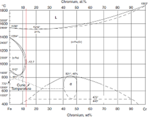
THE Fe - Cr SYSTEM:
P>One of the most suitable FNR initial fuel tube components is iron. At temperatures below 460 degrees C the Fe-Cr system has a stable BCC crystal lattice configuration at all Fe/Cr ratios.
If the fuel tube crystal lattice is initially FCC there will soon be a transition to BCC which reduces the fuel tube material density by a factor of two and which causes a linear swelling dimension increase factor of 1.26. This material swelling will obstruct the primary liquid sodium circulation. To minimize the fuel tube swelling the fuel tube alloy lattice must always be BCC because a BCC lattice is less dense than a FCC lattice. The solution to this problem is to fabricate the fuel tubes from (Fe + Cr) that are initially BCC and have no lattice phase change in the temperature range of interest.
The optimum Fe - Cr fuel tube life maximization strategy is to start with nearly pure Fe and add enough Cr to stabilize the material in the (alpha + alpha prime) zone. Hence at the start of fast neutron exposure the fuel tubes consist of:
85% Fe + 12% Cr + 3% other.
Ensure that the Fe - Cr fuel tube alloy is free of nickel, which has a relatively large fast neutron scattering cross section. Minimizing nickel concentration avoids formation of long half life Ni-59 which is a waste disposal problem.
The amounts of Be, and C present must also be minimized because they lead to formation of long lived isotopes Be-10 and C-14.
The normal low temperature crystal structure of pure iron is BCC with one side of a cube unit cell
= 286.65 pm.
However, from 912 deg C to 1394 deg C the crystal structure of iron becomes FCC with one side of a cube unit cell
= 286.65 pm
The Fe - Cr system has two BCC phases designated alpha and (alpha + alpha prime). The initial chromium (Cr) concentration in a fuel tube must be set at 12% to keep the fuel tubes in the alpha phase throughout most of their length and throughout their working life.
Successful FNR fuel tubes have been made with an initial component ratio of 85% Fe, 12%Cr, 3% other alloy known as HT-9.
The HT-9 alloy has a BCC crystal structure throughout its contemplated working temperature and component ratio range.
Below is the Fe-Cr alloy phase diagram with a red line showing the position of HT9 on that diagram. Note that over the temperature range from about 460 deg C up to the alloy melting point at about 1500 deg C HT9 remains in the alpha phase with a BCC crystal lattice. The bottom of the fuel tubes will frequently be as cool as 340 deg C and hence require periodic annealing.
Accumulation of lattice dislocations causes HT9 fuel tube embrittlement at lower operating temperatures (330 degrees C to 425 degrees C). However, there is experimental evidence that the lattice dislocations anneal out at 650 degrees C.
NEUTRON ACTIVATION OF Fe AND Cr:
Stable Fe-54 + n becomes unstable Fe-55 which positron decays to stable Mn-55;
Stable Fe-56 + n becomes stable Fe-57;
Stable Fe-57 + n becomes stable Fe-58;
Stable Fe-58 + n becomes unstable Fe-59 which decays by electron emission into stable Co-59.
Stable Mn-55 + n becomes unstable Mn-56 which decays by electron emission into stable Fe-56 .
Stable Cr-52 +n becomes stable Cr-53;
Stable Cr-50 + n becomes unstable Cr-51 which decays by electron emission into Mn-51 which then decays by positron emission into stable V-51;
Stable Cr-53 + n becomes stable Cr-54;
Stable Cr-54 + n becomes unstable Cr-55 which decays by electron emission into stable Mn-55.
Thus a fuel tube initially composed of a Fe + Cr alloy appears from a neutron activation perspective to be very good.
FNIPA:
Fast Neutron Reactor (FNR) tube wear can be expressed in terms of number of fast neutron scattering impacts per fuel tube atom (fnipa).
The number of fast neutron impacts per fuel tube atom (fnipa) can be calculated by starting from the reactor power level, finding the rate of neutron impacts on fissionable atoms, and using relative fast neutron scattering cross sections of fuel tube atoms to find the rate of fast neutron impacts on FNR fuel tube atoms.
Brookhaven elastic and inelastic neutron scattering data for Fe-56 and average fission neutron energy data indicates that Nk > 7. In doing this calculation we can assume that within a particular fuel tube bundle the various atomic types are uniformly distributed within the critical portion of the fuel bundle volume.
DEFINITIONS:
N = number of fast neutrons randomly moving through the fuel bundle
Np = number of Pu atoms in the fuel bundle;
Vol = volume of fuel bundle;
Sigmaf = 1.7 b = plutonium fission core neutron cross section;
Ef = energy release per Pu atom fission
P = thermal power of fuel bundle;
Ni = number of iron atoms in the fuel bundle;
Nn = nimber of nickel atoms in the fuel bundle;
Nc = number of chromium atoms in the fuel bundle;
Sigmais = 3.8 b = iron atom core neutron scattering cross section;
Sigmaia = 0.0086 b = iron atom core neutron absorption cross section;
Sigmacs = 4.2 b = chromium atom fast neutron scattering cross section;
Sigmaca = 0.014 b = chromium atom fast neutron absorption cross section;
Vn = neutron velocity;
Mp = 0.072409 kg = mass of plutonium;
Mi = mass of iron
= [Pi / 4][(0.5 inch)^2 - (0.37 inch)^2](.0254 m / inch)^2 [0.45 m](7.874 gm / cm^3)(1 kg / 1000 gm)(10^6 cm^3 / m^3) X 0.88 = 0.1787 kg;
Mc = mass of chromium
= [Pi / 4][(0.5 inch)^2 - (0.37 inch)^2](.0254 m / inch)^2 [0.45 m](7.874 gm / cm^3)(1 kg / 1000 gm)(10^6 cm^3 / m^3) X 0.12 = 0.02436 kg;
Wp = 239 = atomic weight of plutonium;
Wi = 56 = atomic weight of iron;
Wc = 52 = atomic weight of chromium.
Consider a single fast neutron passing through the fuel bundle. The number of fissions per unit time due to this single neutron is:
[(Sigmaf Np Vn) / Vol]
The number of fast neutron scatters per unit time off iron atoms due to a single neutron is:
[(Sigmais Ni Vn) / Vol]
The number of fast neutron scatters per unit time off chromium atoms due to a single neutron is:
[(Sigmacs Nc Vn) / Vol]
Np = [(mass of plutonium) / (atomic weight of plutonium)] X 6.023 X 10^23
= Mp / Wp
Ni = [(mass of iron) / (atomic weight of iron)] X 6.023 X 10^23
= Mi / Wi
Nc = [(mass of chromium) / (atomic weight of chromium)] X 6.023 X 10^23
= Mc / Wc
Hence the number of fast neutron scatters off fuel tube atoms per fission is:
[(Sigmais Ni) + (Sigmacs Nc)] / (Sigmaf Np)
= [(Sigmais Mi / Wi) + (Sigmacs Mc / Wc)] / (Sigmaf Mp / Wp)
= [(3.8 b (0.1787 kg) / 56) + (4.2 B (0.02436 kg) / 52)] / (1.7 b (0.072409 kg) / 239)
= [0.012126 + 0.0019675385] / (5.15043 X 10^-4)
= 27.2638
However, since only (3 / 4) of the original Pu fissions the average number of fast neutron impacts per fuel tube atom in the reactor core region is:
(3 / 4) X 27.2638 = 20.52
On a per neutron basis that is 7 fuel tube atom strikes / neutron.
Brookhaven fast neutron elestic and inelastic scattering data for Fe-56 indicates that Nk ~ 7.
Hence the fuel tubes can withstand about:
7 (0.37) fnipa = 2.59 fnipa
before fuel tube swelling becomes a concern.
Judging by the storage margin the fuel tubes are probably good to past 3.0 fnipa.
The fuel tube rating places an upper limit on the fuel burn-up fraction per FNR fuel cycle.
Thus the fast neutron damage that fuel tubes initially consisting of (85% Fe + 12% Cr) can absorb without significant swelling is Nk (0.37) fast neutron impacts per fuel tube atom (fnipa).
Thus the fuel tube will not accommodate wear above Nk (0.37) fnipa.
Hence for HT-9 fuel tubes fuel tube swelling is not a life limiting factor. The fuel tube working life will instead be limited by Pu depletion and fission product accumulation.
END CAP ISSUE:
One of the potential points of fuel tube leakage is at the end cap weld. If the bottom cap leaks the leaking material will include fission products likely compounded with liquid sodium. If the top cap leaks, and the leak is small, the escaping atoms will likely be the inert gases Ar, Kr and Xe. These radioactive gases will mix with the Ar cover over the sodium pool, which is a difficult to manage problem. The best solution is to have no fuel tube top caps leaks at all. Hence from a fuel tube fabrication perspective the top caps should be applied first and the caps rigorously tested with a helium leak detector. Hence the fuel tube should be assembled upside down. If the bottom cap weld has a small leak it is more difficult for liquid sodium atoms to escape than for an inert gas molecules to escape from a similar size leak in the top cap weld.
Each fuel tube should be tested with He to determine if there are any radial leak imperfections.
This web page last updated June 11, 2023.
| Home | Energy | Nuclear | Electricity | Climate Change | Lighting Control | Contacts | Links |
|---|